Every data centre with a raised floor has a number that rarely gets discussed after the building is constructed: the plenum depth. That is the distance between the structural slab and the underside of the raised floor tiles. It is set during construction and, in most facilities, it never changes.
That number determines how much cooling your raised floor can deliver. Not the CRAC units. Not the chilled water plant. The plenum depth sets the ceiling on how much airflow the floor system can distribute to the racks, and many facilities are hitting that ceiling without realising it.
This post explains the physics behind plenum depth, how it affects tile output and cooling capacity, and what operations teams can do when the floor height limits their cooling potential.
Why Plenum Depth Matters
The raised floor plenum works like a pressurised duct. CRAC or CRAH units push cold air into the plenum. That air travels under the floor and exits through perforated tiles into the cold aisles. The pressure that drives the air through the tiles is called static pressure, and it is determined by three things: the volume of air the CRAC units push into the plenum, the total open area in the floor (tiles, cutouts, and leaks), and the depth of the plenum.
Deeper plenums hold a larger volume of air. That larger volume acts as a pressure buffer. It smooths out velocity variations, reduces turbulence, and allows air to distribute more evenly across the floor before exiting through the tiles. The result is more consistent airflow at every tile position, higher tile output, and better cooling delivery to the racks.
Shallow plenums have less volume and less buffering capacity. Air enters the plenum from the CRAC unit at high velocity and does not have enough space to decelerate and spread before it reaches the tiles. Tiles near the CRAC unit receive excessive airflow (sometimes creating cold spots and wasted capacity). Tiles far from the CRAC unit receive less airflow because the pressure drops off with distance. The result is uneven cooling delivery across the data hall.
The Numbers: Plenum Depth vs Tile Output
Published engineering data from ASHRAE, Uptime Institute, and cooling system manufacturers provides reference values for how plenum depth affects tile performance. The relationship is not linear, but the general pattern is consistent:
300 mm (12 inches) plenum: Common in older facilities and smaller server rooms. This depth supports light to moderate density loads (3 to 5 kW per rack) but struggles with anything higher. Static pressure is low, and tile output drops significantly at positions more than 5 to 6 metres from the CRAC unit. Airflow uniformity across the floor is poor.
450 mm (18 inches) plenum: A middle-ground depth found in many facilities built in the 2000s. This depth supports moderate density (5 to 10 kW per rack) with reasonable uniformity if tile placement and CRAC positioning are well managed. It is adequate for general-purpose compute but begins to limit performance at higher densities.
600 mm (24 inches) plenum: The depth recommended by most current design guides for new data centre construction. This depth provides enough volume for consistent static pressure across a typical data hall footprint. It supports higher density loads (10 to 15 kW per rack) and provides headroom for future density growth.
900 mm (36 inches) and above: Found in large enterprise and hyperscale facilities. These depths provide excellent pressure uniformity and support the highest air-cooled density configurations. The additional depth also accommodates sub-floor cable routing with less airflow obstruction.
The key takeaway: every 150 mm of additional plenum depth improves airflow uniformity and increases the effective cooling capacity of the floor system. Facilities with shallow plenums are working harder to deliver less cooling.
What Happens When the Floor Is Too Shallow
A facility with a 300 mm plenum and growing rack densities hits the wall in predictable ways.
Hot spots appear far from CRAC units. The tiles closest to the CRAC output receive adequate airflow. The tiles at the far end of the aisle receive less. Racks in those positions run hotter. The operations team responds by lowering the CRAC supply temperature, which increases energy consumption without solving the distribution problem.
Overcooling near CRAC units. To compensate for inadequate airflow at distant positions, teams overcool the entire supply. Racks near the CRAC units receive air that is colder than necessary, wasting energy. The facility PUE rises even though the total cooling capacity is sufficient.
Tile output drops under load. As more tiles are opened to serve additional racks, the total open area in the floor increases, which reduces static pressure. Each tile delivers less airflow. The system enters a negative feedback loop: more tiles produce less output per tile, which creates more hot spots, which prompts more tiles to be opened.
Cable congestion compounds the problem. In facilities that route cables through the plenum, the cables create physical obstructions that further restrict airflow. The effective plenum depth in cable-congested zones can be significantly less than the measured depth. A 450 mm plenum packed with cables may perform like a 250 mm plenum.
What Operations Teams Can Do
You cannot change the plenum depth after construction (short of a major structural renovation, which is rarely justified). But you can optimise what the existing plenum delivers.
Maximise Static Pressure
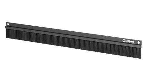
Every unnecessary opening in the floor bleeds pressure. Solid tiles should replace perforated tiles in positions where no cooling is needed (hot aisles, empty aisles, decommissioned zones). Cable cutouts should be sealed with brush grommets that maintain cable access while closing the air gap. Edge gaps around tiles and floor perimeters should be sealed with gaskets or foam tape.
The goal is to reduce the total open area in the floor to only the tiles that are actively delivering cooling to racks. Every sealed opening recovers pressure for the tiles that remain.
Use Directional Tiles
Standard perforated tiles release air in all directions. In a shallow plenum where pressure is already low, that undirected airflow disperses quickly and loses effectiveness before reaching the rack inlets.
Directional airflow tiles focus the air exit toward the rack face, increasing the usable airflow at the server intake without requiring higher plenum pressure. In shallow plenum environments, directional tiles can recover 20 to 40% of the effective cooling delivery compared to standard perforated tiles at the same position.
Tune Dampers Position by Position
In facilities with adjustable floor tile dampers, tuning the damper opening at each position allows you to redistribute airflow based on actual rack loads. Setting dampers wider for high-density positions and narrower for low-density positions balances the delivery without changing the total open area.
This is particularly effective in shallow plenum environments where pressure uniformity is poor. By restricting flow at over-served positions (near CRAC units), you increase pressure available for under-served positions (far from CRAC units).
Clear Sub-Floor Obstructions
If cables are routed through the plenum, evaluate whether they can be relocated to overhead cable trays. Every bundle of cables removed from the plenum recovers effective depth and reduces turbulence. This is a disruptive project in a live facility, but even partial cable relocation (starting with the densest congestion zones) can improve airflow measurably.
Add Supplemental Cooling for High-Density Zones
When the raised floor system cannot deliver enough airflow to specific high-density zones, in-row or overhead cooling units can supplement the floor delivery. These units bypass the plenum entirely, delivering cold air directly to the rack intakes from units positioned within the row.
This hybrid approach lets the raised floor handle the base load while the supplemental units handle the density peaks. It is a practical solution for facilities where the plenum cannot support the highest-density racks but works adequately for the rest of the floor.
Plenum Depth and Containment
Containment improves cooling performance in any raised floor environment, but it is especially valuable in shallow plenum facilities.
Without containment, cold air exits the tiles and must travel from the floor to the top of the rack (1.8 to 2.1 metres) before being drawn into the server inlets. In a shallow plenum with low tile output, much of that air disperses or mixes with hot exhaust before reaching the upper rack units.
With cold aisle containment, the cold aisle becomes a pressurised enclosure. Even modest tile output builds up within the contained space, creating a reservoir of cold air that feeds every rack position from floor to ceiling. The containment compensates for the low tile velocity by trapping the air where it needs to be.
For facilities with shallow plenums, containment is not just an efficiency measure. It is a capacity recovery tool that can extend the useful life of the cooling infrastructure.
Design for the Future
If you are involved in specifying a new data centre or a major renovation, make the case for a deeper plenum. The marginal construction cost of going from 450 mm to 600 mm is small relative to the total project budget. The cooling capacity and flexibility that additional depth provides will pay for itself many times over during the facility’s 15 to 20 year operational life.
The density trajectory in the industry is clear: rack loads are rising. AI, GPU compute, and edge consolidation are all pushing power and heat per rack upward. A deeper plenum gives the raised floor system more headroom to handle those increases without requiring supplemental cooling hardware.
Contact EziBlank to discuss floor tile solutions for your raised floor environment.