
Data centre teams spend significant time and money on cooling system capacity. They spec CRAC units, size chilled water plants, and calculate total heat rejection requirements down to the kilowatt. They invest in containment, blanking panels, and monitoring software.
Then they install the floor tiles wherever it is convenient and never think about them again.
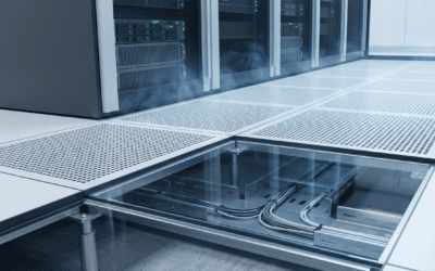
This is a problem. Because in a raised floor environment, the floor tile is the last mile of the cooling delivery system. It is the point where cold air exits the plenum and enters the data hall. And just like the last mile in a logistics network, it is where the most value is lost or gained.
Misplaced floor tiles waste cooling capacity. Correctly placed and configured tiles can recover performance that teams assumed required additional cooling hardware. This post explains why tile placement matters more than most people think, and how to audit and correct it in your facility.
The Physics of Tile Placement
In a raised floor data centre, cold air travels through the sub-floor plenum under positive pressure. It exits through perforated or grated floor tiles and rises into the cold aisle. Servers draw that air through their front intakes.
The goal is simple: deliver cold air to the server inlets at the right temperature and volume. Every tile that is not positioned to achieve this goal is wasting cooling capacity.
Where Tiles Go Wrong
Tiles in the hot aisle. This is the most common and most wasteful placement error. A perforated tile in the hot aisle delivers cold air directly into the hot exhaust stream. The cold air mixes with the hot air immediately, raising the return air temperature to the CRAC unit (reducing its efficiency) while contributing nothing to server cooling.
In facilities without containment, hot aisle tiles are sometimes placed intentionally to “cool down the hot aisle” for technician comfort. This is understandable from a human perspective but disastrous from an efficiency perspective. That tile’s entire airflow output is wasted.
Tiles too far from rack intakes. Cold air exits a standard perforated tile and rises vertically with some lateral spread. If the tile is positioned more than 60 to 90 centimetres from the rack face, a significant portion of that airflow disperses into the room before reaching the server intakes. The farther the tile from the rack, the more the air warms and the more volume is lost to mixing.
Too many tiles for the load. More tiles means more total open area in the floor, which means lower plenum pressure. Lower plenum pressure means every tile delivers less airflow. In zones with light IT loads, excess tiles rob pressure from high-density zones that need it. The result: the high-density racks starve while the low-density racks receive more cooling than they need.
Too few tiles for the load. The opposite problem. High-density racks without enough tile output in front of them will pull makeup air from wherever they can get it, including from the hot aisle. This is how hot spots form in facilities that appear to have adequate total cooling capacity.
The Audit Framework
Correcting tile placement starts with understanding where tiles are, what they deliver, and whether that delivery matches the heat load at each rack position.
Step 1: Map Every Tile
Walk the data hall and document every floor tile location. Mark each tile as solid, perforated (standard), perforated (high-output), directional, grated, or cable cutout. Note any tiles with visible damage, misalignment, or gaps at the edges.
This sounds tedious. It is. But most facilities do not have an accurate tile map, and decisions made without one are guesswork.
Step 2: Map the Heat Load
Document the actual power draw (or nameplate rating if actual draw is not measured) for every rack in the facility. The goal is to match cooling delivery (tile output) to cooling demand (rack heat load) at each position.
Step 3: Compare Delivery to Demand
For each rack position, estimate the airflow volume delivered by the tiles in front of it. Standard 25% open perforated tiles deliver roughly 400 to 600 CFM at typical plenum pressures. High-output directional tiles deliver more by controlling the air exit angle and reducing dispersion.
Compare the estimated tile output to the airflow required by the rack. A rough rule: each kilowatt of IT load requires approximately 120 to 160 CFM of cooling air (depending on temperature differential targets). A 10 kW rack needs roughly 1,200 to 1,600 CFM. If the tiles in front of it deliver 500 CFM, that rack is pulling the remaining 700 to 1,100 CFM from somewhere else, and that somewhere else is usually the hot aisle.
Step 4: Identify Mismatches
The audit will reveal three types of mismatches:
Over-served positions: Low-density racks with too many tiles. These positions are receiving more cooling than they need, and the excess open area is reducing plenum pressure for the rest of the floor.
Under-served positions: High-density racks without enough tile output. These are the hot spot candidates.
Misplaced tiles: Tiles in hot aisles, tiles in empty aisles, tiles in front of decommissioned racks. Every misplaced tile is an air leak that reduces plenum pressure and wastes cooling capacity.
Step 5: Rebalance
Move tiles from over-served positions to under-served ones. Replace standard perforated tiles with directional tiles in front of high-density racks to increase usable airflow without adding more open area to the floor. Swap perforated tiles in the hot aisle for solid tiles. Seal cable cutouts with brush grommets to recover the lost pressure.
This rebalancing exercise costs very little. Tiles are movable. The labour is minimal. But the thermal impact can be significant.
The Damper Variable
Many modern floor tiles include adjustable dampers that control the percentage of open area. A tile with a fully open damper delivers maximum airflow. A tile with a partially closed damper delivers less.
Dampers allow fine-tuning of airflow delivery at each tile position without moving tiles. Configuring dampers for high-density zones is one of the most effective and least expensive ways to optimise cooling in a raised floor environment.
The concept is straightforward: open dampers wider in front of high-density racks. Close them partially in front of low-density racks. The total open area across the floor stays the same (preserving plenum pressure), but the distribution shifts to match the actual heat load.
In practice, damper adjustment requires measurement. Set the dampers, measure the inlet temperatures, adjust again. It is iterative, but each iteration moves the thermal profile closer to the target. Facilities that invest an afternoon in damper tuning often see inlet temperature variance drop from 8 to 12 degrees Celsius to 3 to 5 degrees across the same row.
What “Good” Looks Like
A well-optimised tile layout has several characteristics:
No perforated tiles in the hot aisle. Zero. If technician comfort is a concern, address it with portable spot coolers or personal cooling equipment, not by bleeding cold air into the exhaust stream.
Tile output matches rack load. High-density racks have more tile output (directional tiles, multiple tiles, wider damper settings). Low-density racks have less. The distribution is proportional to the heat load.
Plenum pressure is consistent. Fewer unnecessary tiles in the floor means higher plenum pressure, which means every remaining tile delivers more airflow. Closing unused tiles and sealing cable cutouts is the cheapest way to boost plenum pressure.
Inlet temperatures are consistent. The end goal is not uniform tile placement. It is uniform inlet temperatures across the facility. When every rack receives cold air at the target temperature (within a 2 to 4 degree Celsius band), the cooling system is working efficiently and hot spots are eliminated.
The Cost of Getting It Wrong
Misplaced tiles do not generate alarms. They do not show up on monitoring dashboards. They do not cause immediate outages. They just quietly waste cooling capacity, day after day, year after year.
A single misplaced tile in a hot aisle might waste 500 CFM of cold air. Multiply that by the number of misplaced tiles in a typical unaudited facility, and you start to see the scale of the problem. That wasted airflow represents cooling energy that the facility pays for but never uses productively.
The fix is not expensive. It does not require new equipment or major capital investment. It requires a floor walk, a map, some measurements, and the willingness to move tiles and adjust dampers based on data rather than habit.