To configure floor tile dampers in a high-density data centre environment, calculate the cooling airflow needed per rack using its power load and temperature delta (ΔT), select a compatible airflow tile based on open area and directionality, install it in the cold aisle in front of the rack intake, adjust damper openness to match CFM delivery, and monitor underfloor static pressure (ΔP) to maintain airflow consistency across rows.
This process ensures airflow is balanced, pressure is stable, and cooling is targeted only where it’s needed, preventing recirculation, air starvation, and overcooling inefficiencies.
What airflow should each rack receive based on its power draw?
Start with this formula:
CFM = (kW × 3412) ÷ (1.08 × ΔT°F)
This converts server power demand into airflow requirements. For example:
- A 10 kW rack at 20°F ΔT requires ~158 CFM
- A 20 kW rack needs ~316 CFM
- A 30 kW rack needs ~474 CFM
This calculation sets the airflow baseline per rack and informs how open the damper under each tile should be. Skipping this step risks overcooling low-density zones and starving high-density racks.
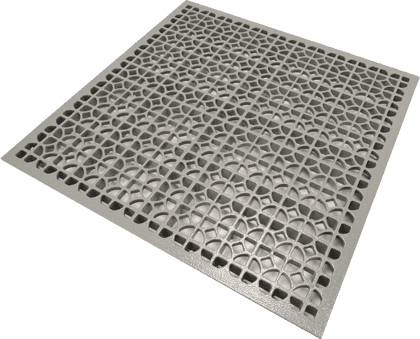
Which airflow tile works best for different density levels?
Not all floor tiles deliver airflow the same way. Use this comparison when selecting tiles:
| Tile Type | Open Area | Best For | Characteristics |
| 25% Perforated | Low | General density zones | Quiet, predictable, low CFM |
| 56%+ High-Flow Grates | High | High-density rows, short rows | High CFM, risk of over-delivery |
| Directional Airflow | Medium–High | Aisles with precise intake targets | Horizontal throw, efficient targeting |
Directional airflow tiles are ideal for narrow aisles or where rack intake alignment matters. At EziBlank, our directional tile range supports controlled airflow delivery that avoids bypassing or short-circuiting.
Where should you place airflow tiles in high-density aisles?
Place tiles only in the cold aisle, directly in front of rack intakes. Avoid:
- Hot aisles (wasted airflow)
- Behind or beside racks (no intake benefit)
- Over-concentrating high-flow tiles in one zone (risk of ΔP drop)
Each tile should align with server intake positions. In taller racks, airflow targeting should cover top, middle, and bottom sections. If airflow is misaligned, servers can overheat or unevenly draw in cool air.
The right hardware for these zones is the Directional High Output Airflow Panel with Damper, paired with the EziBlank High Airflow Floor Tile in surrounding tiles to balance the row.
How should dampers be set to balance airflow delivery?
Adjust each damper to match the airflow required for its corresponding rack. Use the CFM figure from your earlier calculation to set openness.
For example:
- 158 CFM → damper 50% open
- 316 CFM → damper 75% open
Sequence:
- Open dampers fully under the highest-density racks
- Gradually restrict dampers in low-demand zones
- Spot-check temperatures at server inlets
- Fine-tune dampers and re-measure airflow
Manual dampers are adjusted in the field. For larger or variable-density spaces, motorized dampers controlled by a BMS platform (such as EkkoSense) can auto-adjust based on sensor feedback.
Why does underfloor static pressure matter for airflow consistency?
Underfloor static pressure (ΔP) controls how evenly air is delivered across tiles. Low ΔP means distant racks may not receive enough airflow. High ΔP causes noise, turbulence, and bypass.
Maintain pressure within a stable range:
- Target range: 0.05–0.10 in. w.g.
- Measure with pressure sensors mounted across the plenum
- Adjust CRAC/CRAH fan speeds if ΔP is unstable
- Add pressure relief tiles (or dump zones) if over-pressurization occurs
Damper settings directly influence ΔP. If too many dampers are open, especially under high-flow tiles, ΔP collapses, starving adjacent racks. Correct balancing preserves system efficiency.
How can you verify airflow delivery matches rack demand?
After adjusting dampers, validate airflow using field tools and rack sensors:
- Inlet sensors: Measure temp at each rack (top, mid, bottom) — target 18–27 °C
- Tile airflow checks: Use a flow hood or anemometer to confirm actual CFM
- ΔP sensors: Monitor underfloor pressure stability across zones
- Noise check: High velocity or whistling near tiles = imbalance or over-delivery
- Temperature spread: Inlet temps across a row should not vary by more than 3–4 °C
Ongoing validation ensures the configuration remains effective as rack loads change.
When should you choose automated vs manual dampers?
| Control Type | Best For | Pros | Considerations |
| Manual Dampers | Static rack setups, small sites | Lower cost, easy to install | Slower to adjust, needs on-site changes |
| Motorized Dampers | Dynamic density zones, colocation | BMS integration, real-time adjustment | Requires sensors and a control system |
In variable-density environments or hyperscale facilities, motorized dampers managed by DCIM or thermal tools like EkkoSense allow intelligent zoning and airflow response, especially under partial load or during equipment turnover.
What causes poor airflow to nearby racks when dampers are misconfigured?
Uneven airflow often stems from:
- One tile is open too far, stealing airflow
- Plenum obstructions (e.g., cable trays) redirecting flow
- Overuse of high-flow tiles
- Unbalanced dampers are causing pressure shifts
- Missing blanking panels are creating bypass paths
Prevent airflow starvation by:
- Using directional panels for horizontal throw
- Closing unused rack space with EziBlank blanking panels
- Installing pressure sensors and balancing dampers based on data
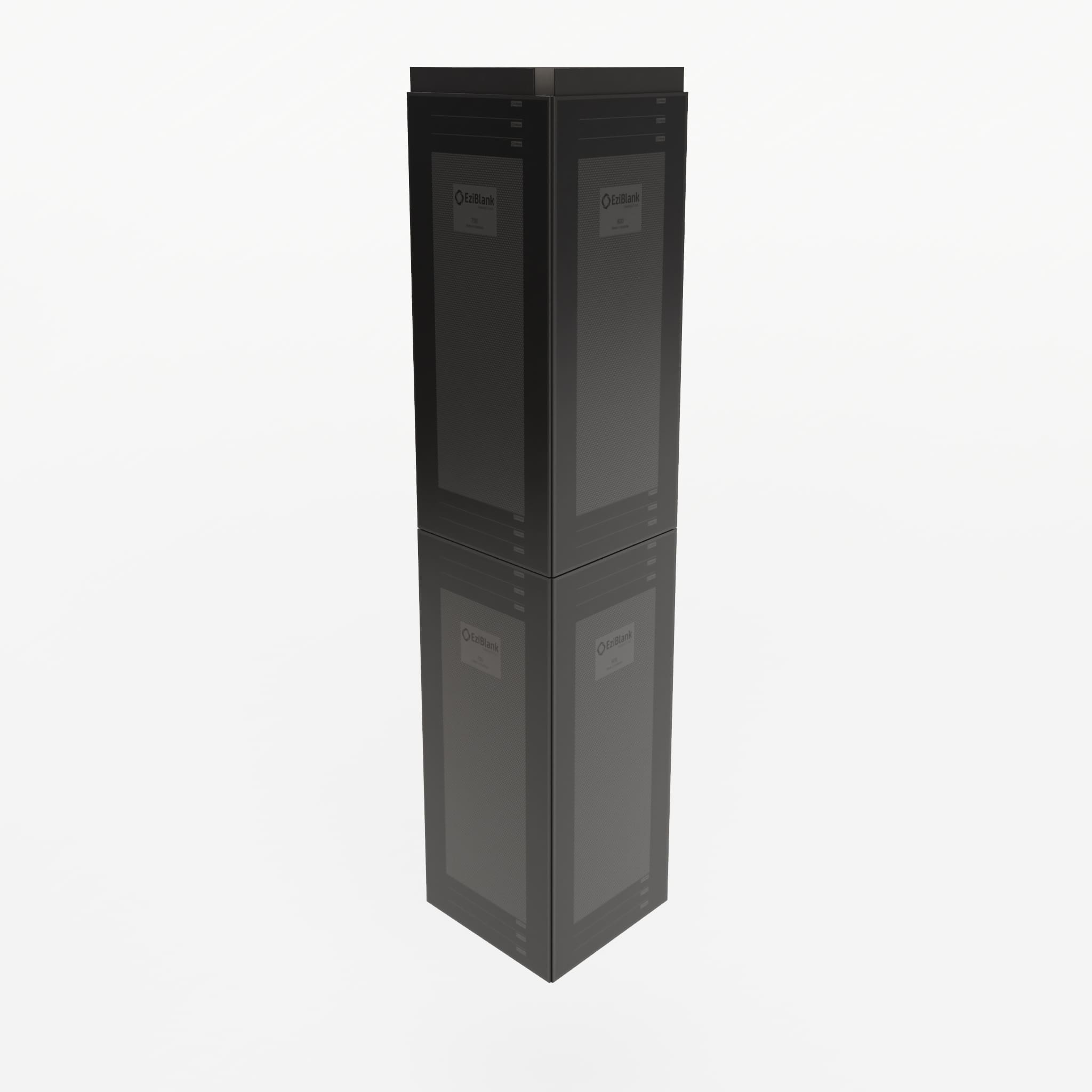
How do containment systems and blanking panels enhance damper performance?
Dampers improve airflow targeting, but containment and blanking panels complete the system:
- Blanking Panels (e.g., EziBlank 6RU, 10SU) eliminate recirculation by closing unused rack spaces, improving airflow efficiency
- Cold Aisle Containment ensures that supply air stays where it’s needed and doesn’t mix with hot return air
- EziBlank Wall Systems offer modular containment that fits seamlessly into existing rack layouts
Together, dampers and containment support controlled thermal zones and reduce cooling loads by up to 30%.
How should you commission and maintain damper configurations over time?
Changes in rack load, layout, or equipment can disrupt airflow balance. Commissioning ensures configurations are correct from day one.
Commissioning Checklist:
- Rack CFM matches calculated demand
- ΔP within target band across entire plenum
- Inlet temperature within 18–27 °C (95th percentile racks)
- Inlet variance across rows ≤ 4 °C
- Dampers correctly adjusted (manual or BMS)
- No airflow tiles in hot aisles
- Noise under threshold (check whistling or high-velocity hiss)
Schedule re-validations quarterly or after major equipment changes. Use tools like Patch Manager to document physical layout and EkkoSense to monitor airflow and alert for imbalances.
What tools can help optimise damper configuration in real-time?
Optimisation platforms can help monitor, balance, and alert:
- EkkoSense: Real-time 3D thermal visualisation and airflow guidance
- Patch Manager: Asset tracking and cable/rack layout documentation
- Tile CFM Calculator: Use airflow calculators based on rack density and ΔT
- Pressure Monitoring Sensors: Real-time ΔP readings for underfloor consistency
Soft call-to-action:
- Download the airflow calculator to determine per-rack damper settings
- Request a damper balancing assessment from your airflow consultant
- View the tile selection matrix to match density levels to tile types
Why EziBlank is trusted for airflow control in high-density cooling environments
EziBlank provides modular airflow solutions that support efficient damper configuration across global data centres. Our directional airflow tiles, reusable blanking panels, and cold aisle containment systems help facility engineers:
- Deliver rack-level airflow precision
- Maintain stable underfloor pressure
- Eliminate bypass airflow
- Adapt easily during retrofits or layout changes
Our products are tool-free, UL94-V0 flame-rated, and compatible with EIA-310-D / ETSI standards. Trusted globally, EziBlank is brought to you by IDC Solutions, enabling data centres to scale with precision, not complexity.